Node Patterns
A node pattern is a picture you build instead of one you pick: drag sketches onto a canvas, chain them through blend and colour nodes, then drive any slider with an audio band or a little script. It saves as a normal .nodes.json pattern and plays like any other effect.
Where node patterns live
Everything starts in the Node Patterns group at the bottom of the pattern library. Its header carries the folder actions and its body lists the graphs you have:
- Link Folder — grant access to a folder of
.nodes.jsonpatterns. The folder is remembered, and once it is linked the button becomes a Linked badge. Linking grants access only: it never loads the folder’s contents. - ADD (New Node Pattern) — open a fresh graph in the editor. A new pattern is written into the linked folder, so ADD stays disabled until you have used Link Folder.
- OPEN (Open Pattern) — add one pattern to your library: it lists the linked folder’s
.nodes.jsonfiles and adds the one you pick. Like ADD it stays disabled until you have used Link Folder, because a pattern is read from, saved to and refreshed in that folder. Adding never opens the editor and never changes what the window shows — the pattern simply joins this group, ready to click and play. - Linked — open the folder details for Refresh, Relink and Unlink. Refresh rereads the patterns you have added (edits and removals on disk) and renews expired access; it never imports a file you have not added — OPEN does that.
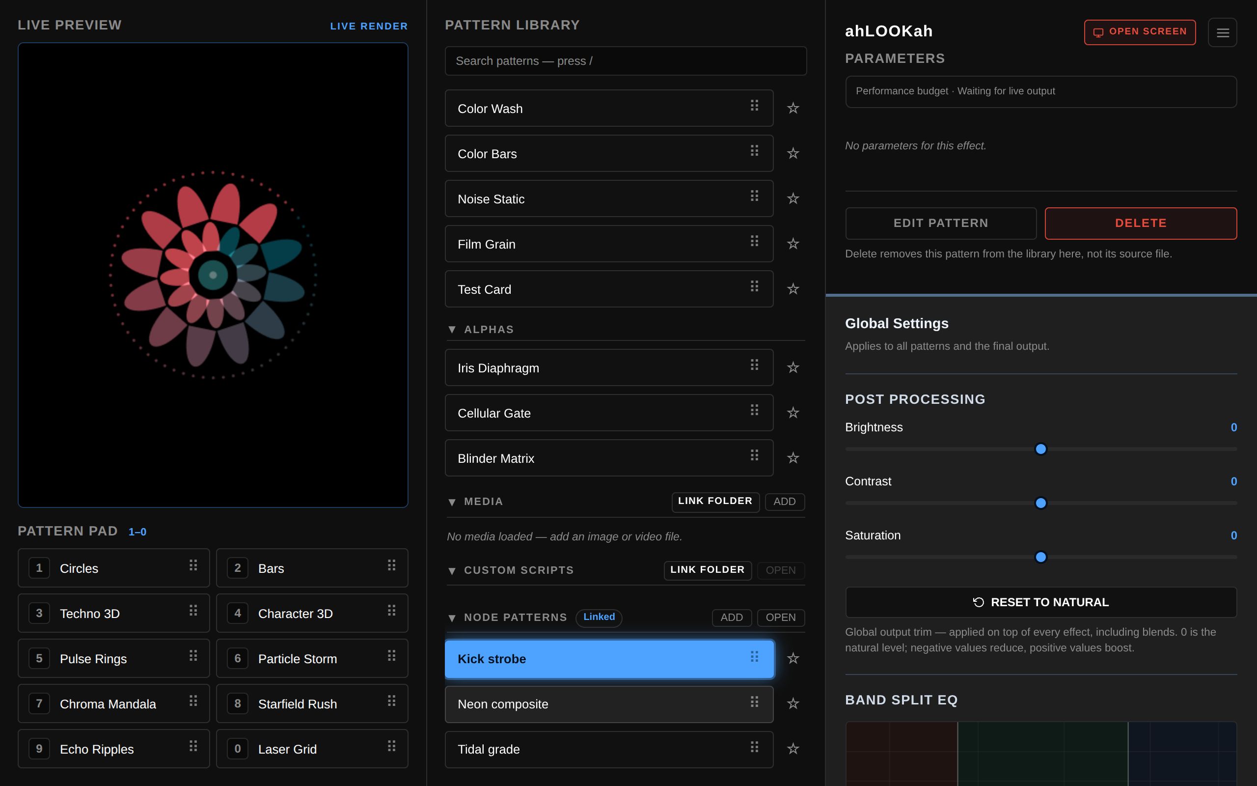
Select a listed graph and its sidebar offers Edit Pattern — the way into the editor from here — and Delete. Delete removes the pattern from this browser’s library only — the file on disk is kept, and OPEN brings it back without opening the editor. Open Project restores exactly the graphs the project recorded, never everything the linked folder happens to hold.
The editor
The editor opens in place over the main app view — no popup, no second tab — and Back to Main returns to the control panel. Leaving a dirty graph asks first. The legacy standalone route still works for direct links: Open Nodes editor.
Three columns: the palette on the left, the canvas in the middle, and the inspector on the right for the selected node.
The inspector’s preview shows the selected node’s own picture, and it can be pinned. Pinned, the window stops following the selection: it keeps drawing the node it was showing, so selecting an Audio, Math, Script, LFO or MIDI node — which carry numbers, never pictures — no longer takes the picture away. The window’s pin sits under it, leaving the heading its node name and IMAGE or SIGNAL label; a pinned window names its node in a small pill beside the pin, and clicking that pill selects it, so the inspector can follow the picture without unpinning it. Pinning from a signal node pins the last image node that was shown (the Output if there was none). The pin is editor state, never graph data: it is not part of the draft, the undo history or the .nodes.json, and it is dropped when its node leaves the graph.
Inspector parameters behave like a photo editor’s sliders: drag one to change it, or double-click it to return that parameter to its default. The parameter’s name, value readout, slider and track all reset it; an option dropdown resets from its name, since its own double click belongs to the open list. Nothing else moves — the other parameters, the node’s wires and any signal mapping stay exactly as they are: on a mapped slider the gesture resets the saved base value underneath (double-click the name or value readout, as the violet overlay keeps its own drag and click gestures) while the mapping keeps running.
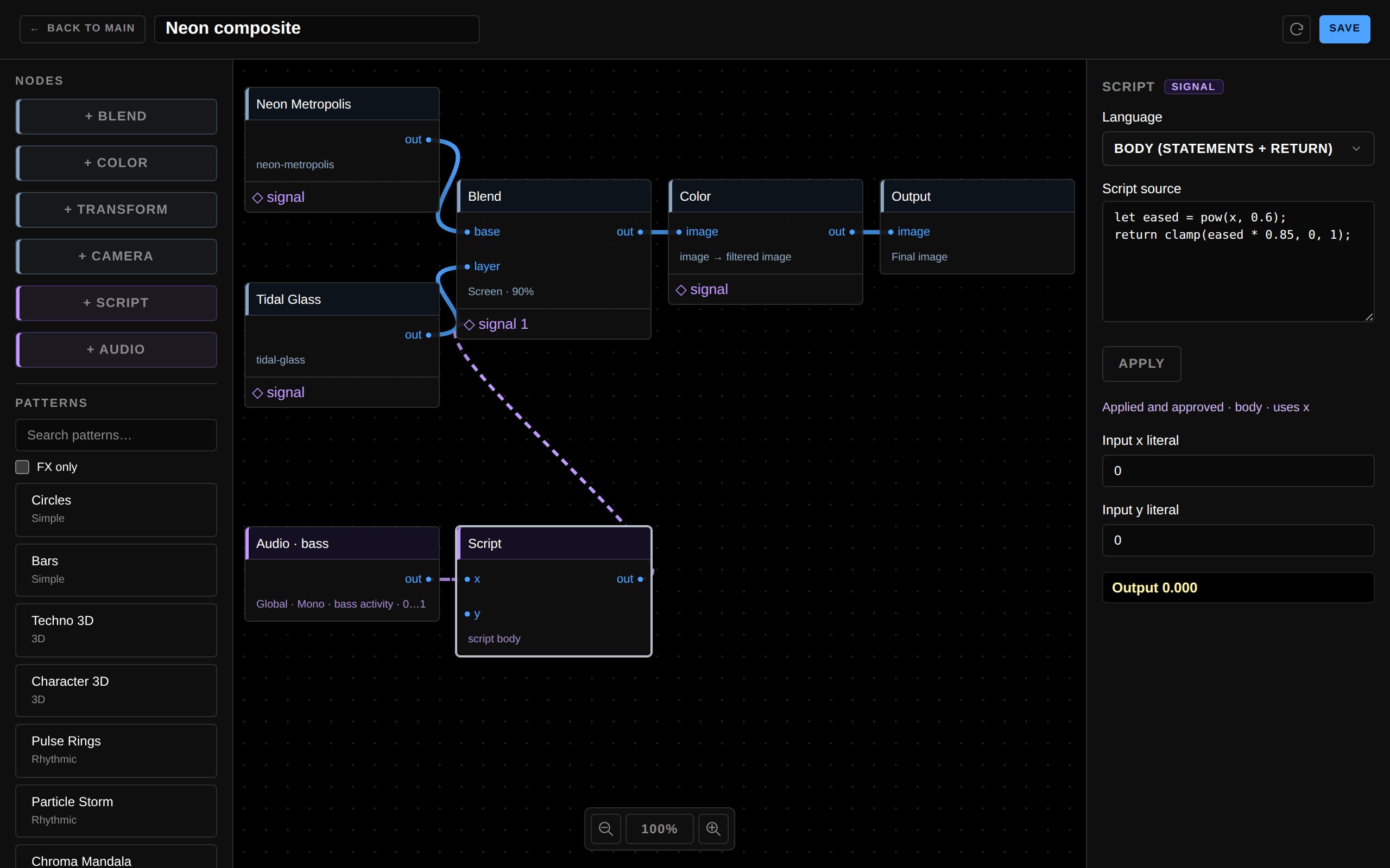
A first graph, in four moves
The simplest useful pattern is one source wired straight to the Output. A new graph starts empty apart from that Output:
- Link Folder on the Node Patterns category, then ADD (New Node Pattern) — ADD stays disabled until a folder is linked, because the new pattern is saved there, and then the editor opens on a blank canvas with a single Output node.
- Drag Circles from the pattern list onto the canvas.
- Click the Circles node’s out ●, then the Output’s ● image. The inspector preview lights up.
- Save, then Back to Main — the graph is now a pattern in your library, ready for the pad or a slot like any built-in.
Everything below is that same move repeated: a second source into ● base and ● layer of a Blend, a Color filter in between, an Audio band into a Script to drive a slider.
Adding nodes
Drag a row onto the canvas — clicking a palette row deliberately does nothing, so a stray click can never create a node:
- Patterns — the searchable list at the bottom of the palette. Every built-in sketch, media pattern, custom script and projection pattern can become a source. A ◇ FX badge marks image-input-capable patterns; FX only filters the list. Drag a pattern onto the canvas: FX-capable patterns have an optional ● image input immediately, with no separate mode control.
- + Blend — composites two images (base and layer).
- + Color — filters an image: saturation, brightness, contrast and hue shift, applied in that fixed order. The identity defaults copy the input pixel-for-pixel, alpha included.
- + Transform — the image node: moves, scales and rotates its input in X, Y and Z with real perspective. Identity copies the input pixel-for-pixel; all nine sliders can be driven by a signal like any other numeric control.
- + Camera — drag an image source onto the canvas. Select Global input (Settings) or pin a specific camera in the Camera node inspector; connect its output to an FX-capable pattern, Blend, Color or Output. Only the output screen owns real capture.
- + Script — a number from the graph’s inputs or the audio bands.
- + Audio — the activity of a bass, mid or high band.
- + LFO — a free-running oscillator that emits a number every frame, for animating any slider without audio or a script. Pick the range (0…1 or −1…1) and the pattern — linear saw, sine, smooth noise, stepped random, or a shape you draw in the inspector — then set the Cycle time from 100 ms to 10 s on a logarithmic track and the Start Position. Cycle time is a rate: changing it, or driving it with a mapped signal, speeds the shape up or slows it down without restarting it. Both sliders are automatable like any other numeric control.
- + MIDI — one channel of a MIDI controller, always emitted as a normalized 0…1 signal. Gate mode turns note on/off into an envelope (Pulse fires one per note and ignores how long the key is held; Sustain follows the held level) with Attack and Decay from 1 ms to 5 s on a logarithmic track and an optional Apply Velocity amount; CC mode returns one control-change value, picked with a number field or Learn CC. Choose the input device (any device, or one pinned controller) and the channel. Configure access once with Enable MIDI — the same permission drives the editor preview and the output screen.
Tip You can also drag a pattern straight from the main library’s pad or list onto the editor canvas; the editor validates what was dropped.
Wiring
Click a source’s out ●, then click the destination’s input — ● base, ● layer or ● image. One wire per input: connecting again replaces what was there. Cycles, and using the Output as a source, are rejected. Drag a node header to move it; a focused header nudges with the arrow keys, and a marquee (or Ctrl/Cmd-click) selects several at once. Ctrl/Cmd+A selects every node on the canvas except the Output, and Delete/Backspace removes the selected nodes or the selected connection. Ctrl/Cmd+Z undoes your last change to the graph and Ctrl/Cmd+Shift+Z (or Ctrl/Cmd+Y) redoes it — no buttons and no menus, because the shortcut is the whole feature. One drag, one slider move or one typed value counts as a single step, redoing is dropped as soon as you edit again, and the name and Script source fields keep their own undo while you are typing in them. The Output is structural: it is never part of a group Delete and is kept even when a marquee or a modifier click includes it.
| Node | Inputs | Output |
|---|---|---|
| Pattern | Optional image (FX-capable patterns only) | Image |
| Camera | — | Image |
| Blend | base, layer | Image |
| Color | image | Image |
| Transform | image | Image |
| Output | image | — |
| Audio | — | Signal |
| Script | x, y | Signal |
| LFO | — | Signal |
| MIDI | — | Signal |
Blend composites two images — ● base first, ● layer second — with an opacity for the layer, and outputs real pixels that can feed further blends, filters and transforms. Exactly one Output node exists; the branch that reaches it is what plays. The mode list follows TouchDesigner’s Composite TOP operations, in two groups:
- Canvas modes — the browser composites these itself, so they cost nothing extra and keep their exact pixels: Normal (TouchDesigner’s Over), Add (Add / Linear Dodge), Multiply, Screen, Overlay, Darken (Dimmest), Lighten (Brightest), Color Dodge, Color Burn, Hard Light, Soft Light, Difference, Exclusion, Under, Inside (Atop), Outside, Xor, Hue, Saturation, Color, Luminosity.
- WebGL2 modes — no canvas equivalent exists, so these run in the graph’s shared WebGL2 compositor: Subtract, Divide, Average, Linear Burn, Vivid Light, Linear Light, Pin Light, Hard Mix, Negate, Reflect, Glow, Freeze, Heat, Darker Color, Lighter Color.
Opacity scales the layer only, and where the base is transparent the layer passes through unchanged rather than being blended against black. Operand order matters for the ordered modes: swapping the wires turns Under into Over, and Subtract into “layer minus base”. The operands are the picture’s colour, straight (not premultiplied) alpha, one channel at a time unless noted:
| WebGL2 mode | b = base, s = layer, per channel |
|---|---|
| Subtract | max(b − s, 0) |
| Divide | s ≤ 0 ? 1 : min(b / s, 1) — a black layer is white, never a divide-by-zero |
| Average | (b + s) / 2 |
| Linear Burn | b + s − 1, clamped to 0…1 |
| Vivid Light | s < 0.5 ? burn(b, 2s) : dodge(b, 2s − 1) |
| Linear Light | b + 2s − 1, clamped to 0…1 |
| Pin Light | s < 0.5 ? min(b, 2s) : max(b, 2s − 1) |
| Hard Mix | b + s ≥ 1 ? 1 : 0 |
| Negate | 1 − |1 − b − s| |
| Reflect | s ≥ 1 ? 1 : min(b² / (1 − s), 1) |
| Glow | b ≥ 1 ? 1 : min(s² / (1 − b), 1) — Reflect with the operands swapped |
| Freeze | s ≤ 0 ? 0 : 1 − min((1 − b)² / s, 1) — inversion of Reflect |
| Heat | b ≤ 0 ? 0 : 1 − min((1 − s)² / b, 1) — inversion of Glow |
| Darker Color | whole-pixel: the operand with the lower luma wins |
| Lighter Color | whole-pixel: the operand with the higher luma wins |
The blend formula is applied where the base is opaque, then the layer is composited over it as usual (αo = αs + αb(1 − αs)), which is exactly what the canvas modes do. TouchDesigner operations with no published formula are deliberately not offered rather than guessed: inverse, subtractive, chroma difference, luminance difference, inside/outside/stencil luminance, Y film and Z film.
Transform (image) node
+ Transform is the graph’s image node: one picture in, the same picture out, moved, scaled and rotated in X, Y and Z with true perspective. Every slider defaults to identity, which copies the input pixel-for-pixel and needs no GPU at all.
| Slider | Range | What it does |
|---|---|---|
| Move X / Y | −2 … 2 | Offset in half-frame units: 1 shifts the picture by half the frame, ±2 clears the frame entirely. |
| Move Z | −1 … 0.9 | Distance along the view axis with the camera one half-frame unit away: +0.5 doubles the picture, −0.5 shrinks it to two thirds. |
| Scale X / Y / Z | −4 … 4 | Scale the plane (negative mirrors). Scale Z squashes the depth axis after rotation, so it bends the perspective of a tilted picture and does nothing to a flat, unrotated one. |
| Rotate X / Y / Z | −180° … 180° | True 3D rotations, applied Z·Y·X: a tilted picture becomes a trapezoid instead of a squashed rectangle. |
Rotation happens in the frame’s own space, so a non-square output stretches a rotated picture. Outside the transformed plane the node is transparent, which is what makes it a useful layer inside a Blend, and what lets a rotated or scaled picture reveal what is behind it. At Rotate X = 90° the plane passes through the camera: the near part is clipped by the GPU instead of wrapping around.
Perspective needs WebGL2. The identity copy, Scale X/Y and Rotate Z are ordinary 2D, but Move Z and Rotate X/Y are the GPU’s perspective. Without WebGL2 the Transform inspector says so and the node passes its image through unchanged, and a WebGL2 blend mode falls back to Normal with a visible note — a machine without a GPU can never look like a broken graph.
Image FX chain: connect a procedural Pattern to Video Chroma Key’s image input, then its output to Video Dots GPU’s image input, then Output. Each wired FX-capable pattern processes its connected image automatically, without requesting its own camera. With no image wire it uses its default camera/source behavior; deleting the wire returns to that behavior. A custom script declaring fx: { input: 'image' } can join the same chain. If a pattern loses FX capability, its saved wire stays visible for repair.
Camera preview in the editor uses a generated sample clip, not a real camera or a permission request. Live camera capture belongs to the output screen. The Camera node’s Camera input device picker is separate: Global follows Settings when the output graph is recreated; pinned device IDs stay pinned, may be unavailable on another machine and need reselection there. Camera → FX chains can be previewed with sample video in the editor and use real capture on the output screen.
Script nodes
A Script turns something the app knows — the audio bands, another node’s value, the clock — into a number. New scripts start in the Body (statements + return) language, a small checked subset of JavaScript that always ends in return:
let eased = pow(x, 0.6);
if (time < 0.5) return 0;
return clamp(eased * 0.8, 0, 1);
Body scripts can declare let/const locals, branch with if/else, compare, use short-circuiting && / ||, the ternary ?: and the usual arithmetic, and call a fixed list of maths functions (sin, clamp, lerp, pow, hypot…) — with the read-only inputs x, y, time and the constants pi, e, tau. Loops, functions, objects, property access and globals are rejected.
Scope is lexical: a let/const belongs to the block it is declared in, an inner block may shadow an outer name but one block cannot declare the same name twice, and the whole block’s declarations are known before it runs — so reading or assigning a name before its own declaration is an error. The inputs, the constants and the function names are reserved and read-only.
Older graphs may use the legacy Expression language — the original one-liner such as sin(time * 2) * 0.5 + 0.5. Files saved before the body language existed carry no language field and keep running as expressions, unchanged.
Press Ctrl+Enter (or click Apply) to validate and store the text in the Script source box; plain Enter adds a line, so bodies stay multi-line. The source is never executed as JavaScript: it is parsed, checked against an allowlist and compiled once into a bounded instruction list the editor runs itself — there is no eval and no generated code. A body is limited to 1024 characters, 512 syntax nodes, 80 statements, 512 instructions, 32 locals, 12 nested block levels and an operand nesting depth of 16; an expression stays at 256 characters, 64 operations and a depth of 12. A script that fails validation cannot be applied or saved, and a runtime error falls back to 0 with a visible message.
Persistent state (state and dt)
A body is otherwise a pure function of its inputs: a let/const is created fresh on every frame. When a value has to survive into the next frame — a smoother, a moving average, a delay line, a counter, a phase — keep it in the node’s own store, state.<name>, and use dt (the seconds since this node last ran) whenever the maths depends on time rather than on frames:
// one-pole smoother, frame-rate independent
state.level = state.level + (x - state.level) * (1 - exp(-dt / 0.15));
return state.level;
Slots are numbers, not objects: state.level + 1, state.level = 2 and state.level += 0.1 all work as expected, and the name is fixed at compile time (there is no state[<expression>], no strings and no methods). Every slot starts at 0, and a slot must be assigned somewhere before it is read — so a typo is a compile error instead of a second, silently zero slot.
A buffer is a bounded window of stored numbers, declared once by assigning an array literal. Its values are the initial contents, applied when the node’s state is created rather than on every frame, and it is read and written with an index:
// weighted average of the last four values (weights 4 3 2 1), a ring buffer
state.hist = [0, 0, 0, 0];
state.i = (state.i + 1) % 4;
state.hist[state.i] = x;
let weighted = state.hist[state.i] * 4 + state.hist[(state.i + 3) % 4] * 3
  + state.hist[(state.i + 2) % 4] * 2 + state.hist[(state.i + 1) % 4];
return weighted / 10;- One update per frame. A node’s body runs at most once for each rendered frame, so
state.n = state.n + 1counts frames. A readout, a mapped slider or any other reader between frames shows that frame’s value instead of running the body again; an unselected branch keeps advancing while it is being inspected. dtis bounded. It is0on the node’s first update and never larger than0.25, so a paused graph, a hidden tab or a branch the renderer does not reach resumes with a small step instead of one huge jump.- A failed evaluation changes nothing. A reported error, a non-finite result or a non-finite stored number leaves the store exactly as it was, so one bad frame can never poison a history.
- Indices are checked. A buffer index is truncated to a whole number and must be inside the buffer (
state.hist[0]…state.hist[3]); an out-of-range index is reported and the node outputs0, so it can never read a neighbouring slot. - State is memory, never file data. Nothing about it is written to the
.nodes.json. It lives as long as the running graph: applying a new source, reloading the pattern or the page, or swapping the live pattern starts from the declared initial values, and the editor preview and the output screen each keep their own. The inspector lists the live slots and buffers of the selected node and its Reset state button restores the declared values. - State follows time, not pixels. A tick that ran advances the store once, whether its image is committed or retired — by an FX tick invalidated halfway through, or by pixels a resize drops. The next frame continues from the stored values with its own small step, so nothing is lost and nothing is counted twice.
- Bounded. All slots and buffers of one node together hold at most 64 values. The legacy Expression language has neither
statenordt: it stays the pure single value it always was.
MIDI nodes
A MIDI node reads one channel of a controller and always outputs a normalized 0…1 signal, so it wires and maps exactly like an Audio band. Pick a Mode:
- Gate (note on/off) — the note becomes an envelope. Pulse fires one envelope per note and ignores how long the key is held (attack up, then decay down, with an 80 ms floor so the 1 ms/1 ms defaults still show a pulse); Sustain follows the held level. Attack and Decay run from 1 ms to 5 s on a logarithmic track, and Apply Velocity blends the envelope toward the note's own velocity (0 = ignore it, 1 = multiply by it fully).
- CC (control change) — the node returns the selected CC number's value, normalized 0…1. Type the number, or click Learn CC and move the control you want to use: the next CC message the node sees sets both its channel and its CC number.
MIDI input device works like the Audio node's: Any device listens to every controller, while a pinned entry follows that one input (an unavailable device stays listed as such instead of silently changing what you hear). Channel picks one of the 16 MIDI channels. Mode, gate mode, channel and device are switches — they are never automation targets.
Because a MIDI node is a signal source and a numeric target, its own sliders take a signal the same way any other slider does: connect a signal to the node's ◇ endpoint, then drag its chip onto Attack, Decay or Apply Velocity. A mapped value arrives in the control's own domain (a logarithmic duration is interpolated logarithmically, so a 10 ms … 1 s mapping passes 100 ms in the middle) and is glided with the same ~80 ms response the LFO uses for its Cycle time — an exponential approach that is frame-rate independent and starts from the value the slider holds, so connecting a signal hands the control over gradually — meaning a steppy source (a random LFO, an audio band, a slow Script) eases the envelope instead of kicking it; a manual slider edit is used exactly as stored. The two modes share the stored values: switching to CC keeps the Attack you set (and vice versa), and a mapping onto a slider the new mode does not show (Attack, Decay or Apply Velocity while CC is selected) is removed with a notice rather than left hidden — it could never be edited or saved otherwise. Access is requested once per window from the inspector (Enable MIDI, then Retry if you denied it), and the browser's own state is spelled out on the node — including "no devices detected" and "this browser has no Web MIDI support".
Driving sliders with audio, scripts and LFOs
Signal outputs are not just for wiring node to node. Select the Script, Audio or LFO node an Audio→Script chain ends in, and the inspector lists it under Connected signals. Drag that chip onto any numeric slider of a selected Pattern, Blend, Color, Transform, LFO or MIDI node to map it:
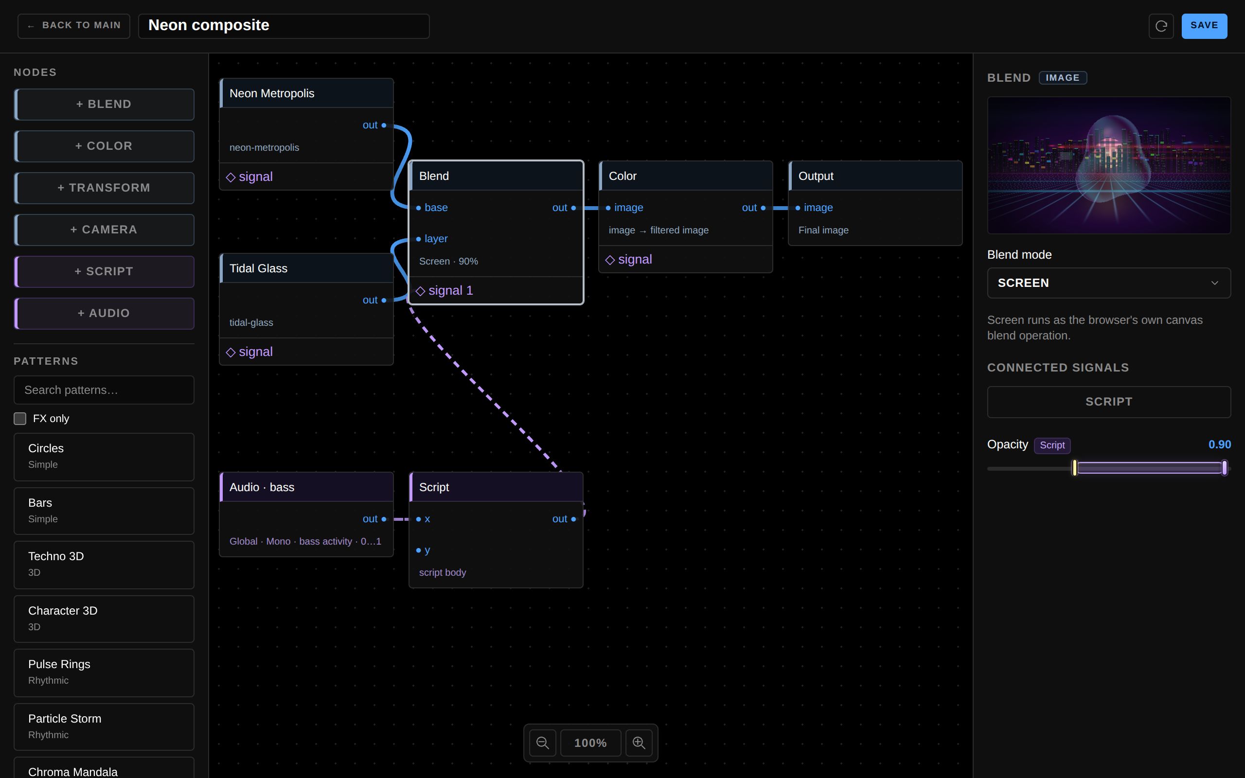
- Range — drag the overlay’s body to slide the range, or its handles to widen it. Mapping min is the slider value at the signal’s low bound, Mapping max the value at its high bound, so a reversed pair sweeps the other way.
- Signal in min/max — convert a different input range (for example a script that outputs 0…4 driving the full slider). Left alone, the range is 0…1.
- Remove mapping — click the overlay to reveal the mapping fields, then remove it; the slider returns to its saved base value.
An LFO is a signal in both directions. It drives anything above, and its own Cycle time and Start Position sliders take a signal the same way — connect the signal to the LFO’s ◇ endpoint, then drag its chip onto the slider. Cycle time is a rate, so automating it accelerates or slows the shape instead of restarting it, and its logarithmic track is interpolated logarithmically when mapped (a 250 ms … 4 s mapping passes 0.5 s in the middle). A new mapping from a bipolar LFO starts at Signal in −1…1, so a −1…1 sweep uses the whole slider; every other source keeps 0…1. Because an LFO is a source and a target, a mapping that would loop back into itself — an LFO on its own Cycle time, or two LFOs driving each other — is refused as a cycle, exactly like a wire loop.
Every mapping is a terminal link in the graph file, saved with the pattern, and one signal can drive many sliders. Enum, boolean and text controls cannot be mapped.
Saving, drafts and going live
The toolbar holds the graph name, Save and Reload from Disk. Saving writes the draft into the linked folder as .nodes.json:
- A draft does not have to be finished. An unconnected Output saves fine and reopens exactly as saved.
- A pattern takes its filename from the linked folder, so it keeps that file even when you rename the graph: Save overwrites the file you opened rather than creating a stray copy.
- Overwriting an existing destination file asks first. A file changed or deleted on disk since you opened it cannot be overwritten — reopen it first.
- A draft that cannot be saved yet says why: the editor and every offending node take a red outline, and the inspector lists the blocking reasons. Deleting the last node that used a removed source clears the block.
Drafts live in memory for the one open editor session and never broadcast edits to the live output — save before closing. Nothing is kept as a hidden second draft, so reopening a pattern always reads the saved graph from disk.
Back in the main app a node pattern behaves like any other: click it to play live, Shift-click to stage it in CUE, drag it to a pad slot, or use it in a merge. Same-origin tabs stay in sync: a confirmed overwrite updates the same pattern id, and a folder refresh is broadcast to the others.
The pattern file
Files are JSON (format: "viz2-nodes"): existing source-only graphs remain version 1; adding a Camera node or connecting an FX-capable Pattern’s image input saves version 2. Files hold the graph, parameter snapshots and a dependency manifest with three independent kinds of link: image edges, scalar signalEdges and terminal modulations.
- Never embedded — media bytes, file handles, script sources and other external assets. The destination needs the same dependencies, and a changed dependency is detected rather than silently substituted.
- Not recursive — a node pattern cannot contain another node pattern; flatten the composition into ordinary sources and blends.
- Bounded — one file or record stays under 200 KB, internal graph images are capped at 1280×720, and a folder keeps up to 64 patterns. Node, source and wire counts are limited only by your machine, not by the app.
Missing files and failed sources show a diagnostic instead of a blank canvas; re-link the file in the main library and reload the draft.